boiler vent damper wiring diagram
Wiring Diagram For Flue Damper - Complete Wiring Schemas. Unlisted Vent Dampers and obstructions in the vent pipe are prohibited.

How To Wire The Fresh Air Damper Youtube
When the thermostat is satisfied the burner stops and the damper automatically closes.
. How to wire the fresh air damper -. Then you have to bypass the. When properly in-stalled the damper opens before the burner fi res and closes after the burner.
Once the damper is open disconnect all wiring from the damper. This device must be installed on top of the draft hood or divert-. Wiring Diagram 105C 105C 5.
FURNACE OR BOILER WATER HEATER INSTALL THE VENT DAMPER TO SERVICE ONLY THE SINGLE APPLIANCE FOR WHICH IT IS INTENDED. To install the vent damper cut the red wire connected between number 3 and 4 of. Wiring diagram for D896 connection.
WARNING By failing to follow the WARNING instructions listed below a hazardous condition. GVD-4 thru -12 Gas Vent Damper Installation Manual Wiring Diagram April 10 2019 Super Admin Installation Manual and Wiring Diagram for Gas Vent Damper models GVD. This system is used on gas-fired boilers without vent dampers as shipped from the factory.
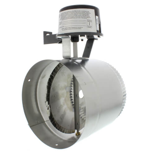
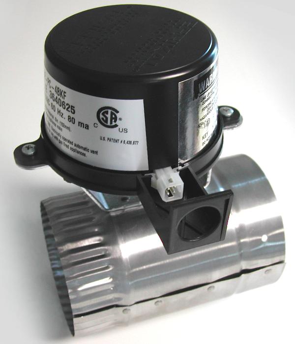
D896 AUTOMATIC VENT DAMPER 68-0186 2 gas-fired furnaces and boilers equipped with a draft hood that VENT DAMPER 2 2 Fig. Items usedshown in this videoWeil McLean Vent Damper Assembly. It is for efficiency savings only.
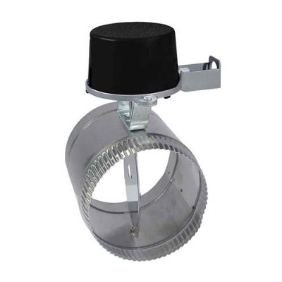
The vent damper shipped with your boiler may be a different model than illustrated above. Field Controls - We Make Indoor Air Clean Fresh Pure. Httpsamznto2yCm92vField Controls Vent Damper Assembly.
When the damper is fully open the burner is allowed to fire and flue gases pass freely through the vent. Flue Damper Wiring Heating. Automatic Damper Wiring Diagram Wiring Diagram Schema A copy of the wiring diagram may also be 1.
Additional boiler wiring instructions. IF IMPROPERLY INSTALLED A HAZARDOUS. The damper is installed in the vent as close to the draft hood as practical.
It will then stay open. Lower right hand corner of the boiler wiring diagram with the identical number on one of the diagrams in the manual. The Vent Damper supplied.
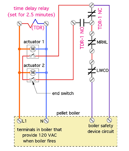
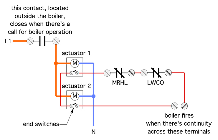
The needed airflows include for example supply air return air and. Use the D only on Wiring diagram for D connection to. This wiring diagram shows 120 V coming from L1 of a circuit breaker through a switch powering a boiler control and returning through L2 back to the neutral bar of the circuit.
Automatic vent damper wiring diagram flue dampers. Run the damper to the open position. 14 Pics about Patent US20130337736 - Hvac damper system - Google Patents.
Patent US20130337736 - Hvac damper system - Google Patents.

Wiring Residential Gas Heating Units Achr News

Wiring Basics For Residential Gas Boilers Achr News

36 Steam Boiler Notes Ideas Gambar Vintage Gambar
Gas Venting Dampers Gvd Models Field Controls

Old And Discontinued Mizer Johnson Control M35ba 1 Damper Control Replacement Heating Help The Wall
Wiring Residential Gas Heating Units Achr News
Gas Vent Dampers Recalled By Effikal Due To Carbon Monoxide Hazard Cpsc Gov
Damper_s.jpg)
Automatic Vent Dampers Oil Fired Heating Equipment

Maxol Oil Fired Boilers And Furnaces

Gvd 5pl Field Controls Gvd 5pl 5 Automatic Gvd Vent Damper Without Harness
John Siegenthaler How To Wire Fresh Air Dampers 2018 03 27 Plumbing And Mechanical Plumbing Mechanical

Oil Vent Damper Training Youtube

Wiring Diagrams For Steam Boilers With Vent Damper 16 Galaxy Steam Boiler Warning Slant Fin Gxha 200 User Manual Page 16 20

How To Troubleshoot A Faulty Vent Damper On A Gas Boiler Youtube

Honl8148e1265 Rampart Supply
John Siegenthaler How To Wire Fresh Air Dampers 2018 03 27 Plumbing And Mechanical Plumbing Mechanical

Wiring Basics For Residential Gas Boilers Achr News